FOSS develops s/w, running in parallel on modern many-GPU HPC systems, for the analysis of turbomachinery components. The figure below shows the time-averaged pressure field computed in a hydraulic turbine application. Water enters the computational domain radially, crosses 24 stationary guide vanes, then 5 rotating runner blades and finally enters axially into the draft tube which is not shown here.
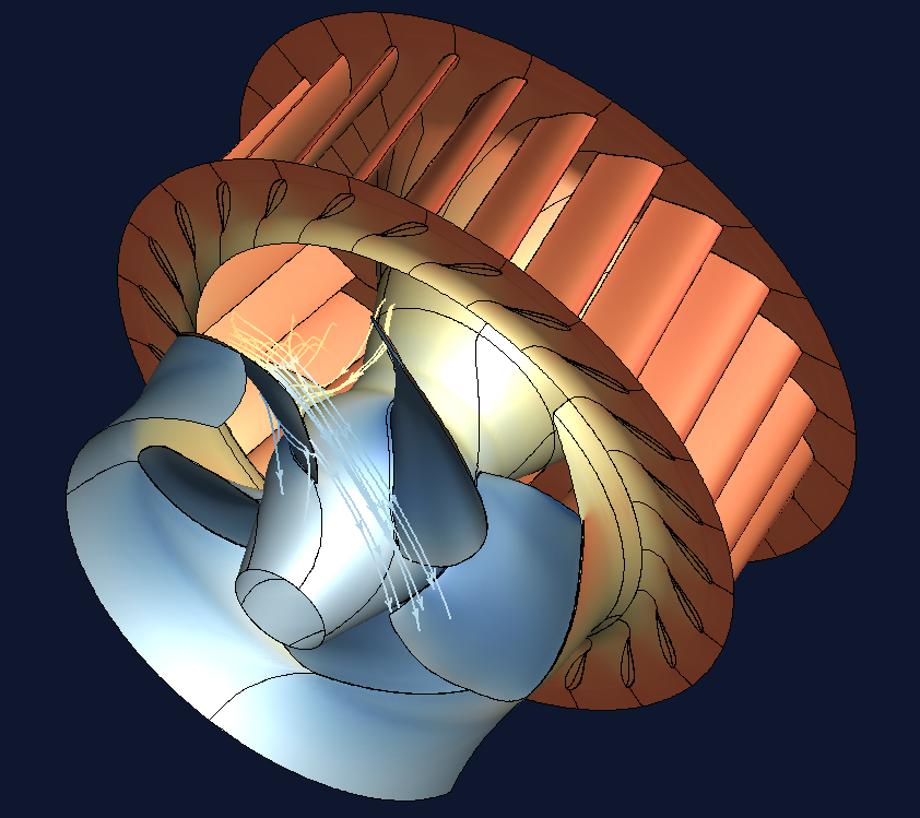
Pressure distribution on a hydraulic turbine.